USB-C Cable Pinout Configuration Complete Guide 2026

Understanding the USB-C Connector Architecture
The USB-C cable connector represents one of the most significant advancements in interface technology over the past decade. Unlike its predecessors, the USB-C (formally known as USB Type-C) features a symmetrical 24-pin design that supports multiple protocols simultaneously through a single compact interface. At Eilinks Electronics, we have been engineering precision USB-C cables since the standard’s inception, giving us deep expertise in pinout configuration and signal integrity.
The 24 pins of a USB-C connector are arranged in two rows of 12 pins each on the top and bottom surfaces of the receptacle. This dual-row architecture enables the reversible plug orientation that users appreciate, while also providing dedicated paths for power, data, and auxiliary functions. Understanding each pin’s role is essential for engineers designing USB-C products and procurement professionals selecting the right cable specifications.
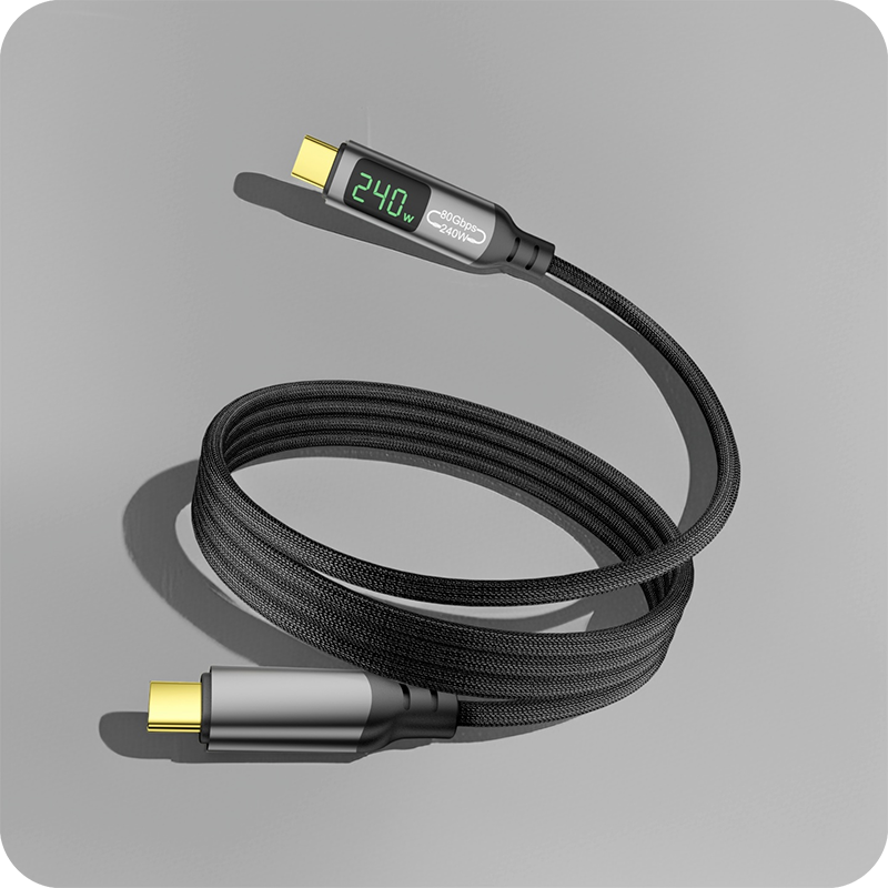
The USB Type-C Specification, maintained by the USB Implementers Forum (USB-IF), defines exact mechanical dimensions, electrical characteristics, and protocol requirements for all 24 pins. As of 2026, the latest revisions support up to 240W power delivery via EPR (Extended Power Range) and data rates reaching 80 Gbps with USB4 Version 2.0.
The 24-Pin Layout Explained
A complete USB-C pinout consists of four functional groups: power delivery pins, high-speed data pins, USB 2.0 data pins, and configuration/control channel pins. Each group serves a critical purpose in ensuring reliable communication between devices.
Power Delivery Pins (VBUS and GND)
The power delivery subsystem uses four VBUS pins (A4, A9, B4, B9) and four GND ground return pins (A1, A12, B1, B12). This quadruple-redundant design allows high-current applications to distribute electrical load across multiple conductors, reducing resistance heat buildup. For EPR-rated cable configurations supporting up to 240W at 48V/5A, the multi-pin VBUS/GND architecture is absolutely essential for safety and efficiency.
High-Speed Data Lanes
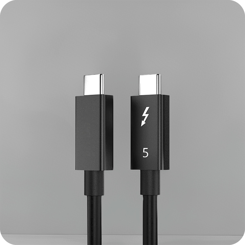
Pins TX1+, TX1-, RX1+, RX1- (A2, A3, A10, A11) and TX2+, TX2-, RX2+, RX2- (B2, B3, B10, B11) form the high-speed differential pairs used by USB 3.x, USB4, Thunderbolt 3, Thunderbolt 4 cable, and Thunderbolt 5 cable protocols. These lanes support lane aggregation, meaning both pairs can operate simultaneously for maximum throughput. In USB4 Version 2.0 mode, these lanes deliver asymmetric speeds up to 120Gbps in one direction and 40Gbps in the reverse direction.
USB 2.0 Data Pins
The D+ and D- pins (A6, A7, B6, B7) carry legacy USB 2.0 data at up to 480 Mbps. These pins are always active regardless of the negotiated high-speed protocol, ensuring backward compatibility with billions of existing USB 2.0 peripherals. Many USB 3.2 Cable products rely on these pins for device enumeration and initial handshake before switching to higher-speed modes.
Configuration Channel (CC) Pins
The CC1 (A5) and CC2 (B5) pins are arguably the most intelligent part of the USB-C pinout. They handle connection detection, role detection (source/sink/dual-role), VCONN power delivery for electronically marked cables (eMarker), and analog audio accessory detection via resistive dividers. Every modern USB-C cable manufacturer must ensure CC pin routing meets strict impedance tolerances.
Sideband Use (SBU) Pins
SBU1 (A8) and SBU2 (B8) are multipurpose sideband pins used for Alternate Mode signaling, including DisplayPort AUX channel communication, HDMI DDC/CEC signals, and Thunderbolt-specific handshaking. When operating in DisplayPort Alt Mode, these pins carry the critical AUX channel data required for link training and EDID exchange between source and display.
USB-C Pinout Configuration Table
The following comprehensive reference table details every pin position, name, color code convention, and primary function according to the latest USB Type-C Specification revision:
| Pin | Name | Type | Primary Function |
|---|---|---|---|
| A1 / B1 | GND | Ground | Power return path for high-current delivery |
| A2 / B2 | TX1+ | Differential TX | High-speed transmit pair 1 positive |
| A3 / B3 | TX1- | Differential TX | High-speed transmit pair 1 negative |
| A4 / B4 | VBUS | Power (4.5-48V) | Main power supply rail for PD charging |
| A5 | CC1 | Config Channel | Connection detect, role detection, eMarker comms |
| A6 / B6 | D+ | USB 2.0 Data+ | Legacy USB 2.0 positive data line |
| A7 / B7 | D- | USB 2.0 Data- | Legacy USB 2.0 negative data line |
| A8 | SBU1 | Sideband Use | Alternate Mode AUX (DisplayPort/HDMI) |
| A9 / B9 | VBUS | Power (4.5-48V) | Main power supply rail (redundant) |
| A10 / B10 | RX1- | Differential RX | High-speed receive pair 1 negative |
| A11 / B11 | RX1+ | Differential RX | High-speed receive pair 1 positive |
| A12 / B12 | GND | Ground | Shield and return path (redundant) |
| B5 | CC2 | Config Channel | Redundant CC for flip detection |
| B8 | SBU2 | Sideband Use | Alternate Mode AUX (secondary) |
eMarker Chip Integration with Pinout
Modern USB4 cable assemblies rated for 100W or above require an embedded eMarker (electronic Marker) chip, which communicates with the host via the VCONN power supply delivered through the unused CC pin. The eMarker reports critical cable attributes including maximum current capacity, supported USB signaling levels (Gen 2/Gen 3/Gen 4), vendor identification, and alternate mode capabilities.
When a host detects a USB-C connection, it applies VCONN (typically 5V at up to 1W) to one of the CC pins. If an eMarker responds with valid identity data, the system knows it is dealing with a passive or active cable with specific capabilities. This mechanism prevents unsafe power negotiation, such as attempting 240W charging through a cable only rated for 60W.
At Eilinks Electronics, our eMarker-equipped cables undergo rigorous testing to ensure accurate reporting across temperature extremes (-20C to +85C) and under sustained load conditions. Our quality control process includes automated eMarker verification at every production stage.
Pinout Considerations for Different USB-C Modes
The versatility of USB-C means different usage scenarios engage distinct subsets of the 24 pins:
USB 2.0 Only Mode
In basic charging and low-speed data scenarios, only the VBUS, GND, D+/D-, and CC pins are actively utilized. This minimal pin engagement is why simple USB 2.0 Cable products can be manufactured with fewer internal wires while remaining fully compliant with USB-C mechanical standards. Many phone chargers, power banks, and basic peripherals operate exclusively in this mode.
USB 3.2 Gen 2×2 Mode
Full USB 3.2 operation activates both high-speed differential pairs (TX/RX) plus the USB 2.0 pins, delivering up to 20 Gbps. A quality USB 3.2 Cable from a reputable USB-C cable manufacturer will have carefully controlled impedance (90 ohms +/- 15%) on all differential pairs to maintain signal integrity at these frequencies.
Thunderbolt 4 / USB4 Mode
Thunderbolt 4 cable operation leverages all high-speed lanes, SBU pins for Thunderbolt protocol handshaking, and the CC pins for advanced authentication. The Thunderbolt certification requires stricter signal integrity margins than baseline USB4, which is why not all USB4 cables qualify as Thunderbolt-certified. Eilinks Electronics manufactures both standard USB4 and fully certified Thunderbolt variants to meet diverse customer requirements.
DisplayPort Alternate Mode
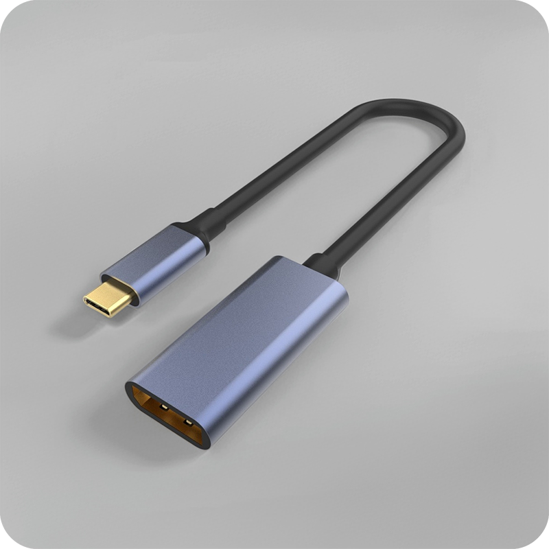
When driving external monitors, USB-C switches to DisplayPort Alt Mode using the high-speed lanes for video payload (up to four lanes of DP 1.4a), SBU pins for AUX channel, and CC pins for HPD (Hot Plug Detect). This configuration supports resolutions up to 8K@60Hz or dual 4K@60Hz displays depending on the cable bandwidth rating.
Manufacturing Quality Factors for Pinout Reliability
Producing USB-C connectors with consistent pinout performance requires precision manufacturing processes. Key factors include:
- Pin coplanarity tolerance: All 24 pins must sit within 0.08mm flatness deviation to ensure simultaneous contact
- Impedance matching: Differential pairs require 90-ohm characteristic impedance with minimal variance
- Shielding effectiveness: The metallic shell provides EMI suppression exceeding -30dB at 5 GHz
- Insertion force consistency: Plug insertion force should remain within 35-75N across 10,000 mating cycles
- Solder joint integrity: Internal PCB-to-wire solder joints must survive thermal cycling without cracking
Eilinks Electronics implements automated optical inspection (AOI) at three separate production stages, combined with X-ray inspection for hidden solder joint defects. Our yield rate exceeds 99.7% after final testing, reflecting our commitment to manufacturing excellence.
Frequently Asked Questions
How many pins does a USB-C connector actually use during normal operation?
During typical charging and data transfer operations, a USB-C connection uses between 6 and 16 pins depending on the protocol mode. Basic USB 2.0 charging uses just 6 pins (VBUS, GND, D+, D-, CC). Full Thunderbolt 4 or USB4 operation engages nearly all 24 pins except for some redundancy in VBUS/GND. The beauty of USB-C is that it automatically negotiates which pins are needed based on the connected devices.
Can a damaged pin in a USB-C cable still allow partial functionality?
Yes, partial functionality is possible depending on which pin is affected. If a single VBUS or GND pin fails, other redundant pins can often compensate due to the multi-pin design. Loss of one differential pair may reduce speed but not prevent operation entirely in many cases. However, damage to CC pins typically results in complete failure because connection detection depends entirely on these pins. We strongly recommend replacing any visibly damaged USB-C cable rather than risking unpredictable behavior.
What is the difference between USB-C pinout and Lightning connector pinout?
The Apple Lightning connector uses 8 digital signal pins in a proprietary arrangement, whereas USB-C uses 24 pins with standardized assignments defined by USB-IF. USB-C supports significantly higher power delivery (up to 240W vs 27W for Lightning), much faster data rates (up to 80Gbps vs 480Mbps), and universal compatibility across manufacturers. The USB-C pinout also supports native video output without adapters, something Lightning requires MFi-certified dongles to achieve.
Why do some USB-C cables only have USB 2.0 speed despite having all 24 pins?
This is a common point of confusion. The physical connector always has 24 pins, but the internal wiring determines actual capabilities. Budget USB-C cables may only connect the USB 2.0 data pins (D+/D-) and omit the high-speed differential pairs (TX/RX) internally, even though the connector shell presents all 24 contact points. Always check product specifications or look for USB-IF certification logos to verify true speed capabilities. Reputable suppliers like Eilinks Electronics clearly label speed ratings on all packaging.
How do I identify if my USB-C cable has proper eMarker functionality?
The most reliable method is using a USB power meter or cable tester that can read eMarker identification data via the CC/VCONN protocol. Visual indicators include checking whether the cable housing has “240W”, “100W”, “40Gbps”, “USB4”, or “Thunderbolt” printed on it, as these markings indicate eMarker presence and reported capabilities. Cables without any wattage or speed marking are typically unmarked passive cables limited to lower power and speed thresholds.